0%

Choosing a 3-axis CNC milling machine starts with the parts you need to make, not the machine’s most impressive specification. Consider the materials, workpiece dimensions, required tolerances, and expected production volume. A small aluminum bracket has different needs from a thick steel plate or a long production run. Small details matter. Check the machine’s travel, spindle speed and power, tool capacity, and table load against real jobs. A machine that looks capable on a brochure may still lack useful clearance or rigidity for your parts. Ask suppliers for specifications, service details, and examples relevant to your application.

The right choice also depends on the people and processes around the machine. Review the control system, programming workflow, installation requirements, operator training, and access to replacement parts. Budget for tooling, workholding, maintenance, and setup—not only the purchase price. Verify important claims with the manufacturer, and request a demonstration or test cut when possible. A clean sample cut is useful, but it cannot guarantee results across every material or setup. Be cautious of choosing by spindle power alone. That shortcut can be tempting. It may overlook stiffness, accuracy, support, or the skills available in your shop. This guide explains how to compare 3-Axis CNC Milling Machines using practical criteria, so you can build a shortlist that fits your work and identify questions worth asking before you commit.
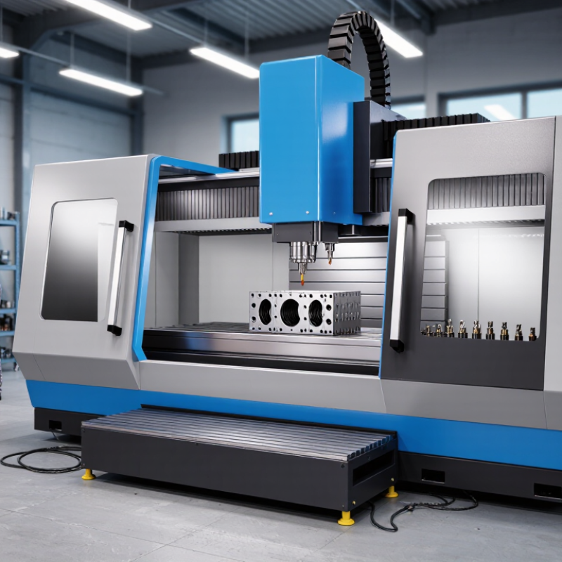
How to Choose a 3 Axis CNC Milling Machine?

Define 3-axis capability through coordinated X, Y, and Z linear motion

A 3-axis CNC milling machine shapes a part through coordinated movement along the X, Y, and Z linear axes. X and Y move the tool or table across the work surface, while Z controls vertical travel toward or away from the material. The machine’s controller combines these movements to follow a programmed path. That matters.

For example, when milling a shallow pocket, X and Y trace its outline while Z sets the cutting depth. Smooth coordination helps produce consistent edges and dimensions. Watch the cut. A machine’s advertised travel limits do not tell the whole story. Check how much usable space remains after fitting a vise, clamps, and the intended tool. Also consider rigidity: a long tool extending far from the spindle can vibrate, even when the axis positions are accurate.

When comparing machines, match their working envelope to the largest parts you expect to mill, then allow room for safe fixturing. Ask how the controller handles coordinated moves and review sample machining results for your material and cutter sizes. I would not judge capability by axis travel alone. That is an easy detail to overlook. Real performance also depends on spindle condition, setup quality, tool choice, and cutting parameters, so confirm the complete setup before assuming a machine will hold a tight tolerance.

Match X/Y/Z travel and table load (mm, kg) to your workpieces

Choose X, Y, and Z travel around the complete setup, not just the part’s dimensions. Include the vise, clamps, rotary fixtures, cutter approach, and room for tool changes. For example, a 420 × 260 × 180 mm housing may need over 500 mm of X travel once clamping space is included. Check Z carefully: fixture height, part height, and tool clearance all use the same vertical travel. A 10–15% allowance can help, but it is a planning margin, not a universal standard.

Table load in kilograms must cover the workpiece, fixture, and clamps together. A 90 kg part on a 35 kg fixture already requires capacity above 125 kg, before considering uneven load distribution. Check the maker’s stated loading method and table limits; a heavy component placed near one edge may behave differently from the same mass centered. Small detail, big consequence.

Accuracy also depends on operating conditions. J. Bryan’s CIRP Annals review of machine-tool thermal effects reports that heat can contribute roughly 40–70% of machine-tool errors in cited studies (1990, vol. 39, no. 2, pp. 645–656). Keep demanding work within the machine’s practical envelope, and allow warm-up time for tight tolerances. The figure is broad, not a guarantee for any one machine. A little humility helps here.

How to Choose a 3 Axis CNC Milling Machine? - Match X/Y/Z travel and table load (mm, kg)

Use the ranges below as an initial screening guide. They are illustrative planning ranges, not specifications for a particular machine. Allow extra room for the fixture, clamps, tool length, and machining approach, and verify the machine’s rated load and usable travel before purchase.

Machine size class Typical X travel (mm) Typical Y travel (mm) Typical Z travel (mm) Typical table-load range (kg) Example workpiece to assess Best suited for
Compact 300–500 200–350 250–400 100–300 About 250 × 150 × 150 mm; up to about 50 kg Small brackets, instrument parts, and light-duty prototypes
General-purpose 600–800 400–500 400–500 300–700 About 500 × 300 × 300 mm; up to about 150 kg Everyday job-shop work, plates, housings, and medium-sized parts
Large-format 1,000–1,300 500–700 500–650 700–1,500 About 900 × 450 × 400 mm; up to about 500 kg Long plates, larger molds, and sizeable machine components
Heavy-duty 1,500–2,000 700–1,000 600–800 1,500–5,000 About 1,400 × 650 × 550 mm; up to about 1,500 kg Heavy fixtures, large castings, and bulky structural parts
Selection checks:
  • Choose travel that accommodates the workpiece and its fixture while leaving clearance for tool access and movement.
  • Compare the complete setup weight—not just the part weight—with the machine’s table-load rating. Confirm any limits on load distribution or center of gravity.
  • Check Z clearance with the actual fixture, tool holder, and longest required tool installed; Z travel alone does not define usable part height.
  • For unusually tall, wide, or heavy workpieces, ask the machine supplier to confirm the setup against the machine’s drawings and load specifications.

Size spindle speed (rpm), power (kW), and torque (N·m) for your materials

How to Choose a 3 Axis CNC Milling Machine?

Choose spindle speed, power, and torque as a matched set. The ASM Handbook, Volume 16, explains that cutting speed depends on the workpiece material, tool material, and operation.

Convert the recommended cutting speed to spindle rpm: rpm = 1,000 × cutting speed (m/min) ÷ π × cutter diameter (mm).

For example, a 10 mm cutter at 100 m/min needs about 3,180 rpm. That is a calculation, not a universal setting. Check the tool maker’s cutting data and allow for setup rigidity.

Power alone can mislead.

Machinery’s Handbook gives the standard relationship: torque (N·m) = 9,550 × power (kW) ÷ rpm.

A 5.5 kW spindle at 3,000 rpm supplies about 17.5 N·m at that operating point. Verify the spindle’s torque curve; rated power may not be available across the full speed range. Aluminum often calls for higher rpm, while steel and large cutters can demand more torque at lower speeds. Watch the chip color, sound, and finish during a test cut. Small details matter.

I would still leave a margin: a machine that meets the calculation on paper may struggle with a long tool, a weak fixture, or a heavy cut.

Compare positioning accuracy and repeatability in μm under ISO 230-2

When comparing a 3-axis CNC milling machine, separate positioning accuracy from repeatability. Accuracy describes how closely the axis reaches a commanded position. Repeatability describes how consistently it returns there. A machine may repeat within 3 μm yet miss its target by 8 μm. Consistent, but not accurate enough for every job.

ISO 230-2:2014 provides a method for testing and reporting numerically controlled axis positioning performance, including bidirectional positioning deviations and repeatability. It does not set one universal acceptance limit for every machine. Ask for the test report, measurement conditions, axis-by-axis results, and measurement uncertainty. A quoted “±5 μm” without test details is incomplete. Small numbers need context.

For a practical comparison, imagine two machines tested over the same 500 mm travel. One reports 6 μm bidirectional positioning deviation and 2 μm repeatability; another reports 4 μm and 5 μm. These illustrative values are not an industry average. The first may return more consistently, while the second may position closer to target overall. Match results to part tolerances, tool length, temperature, and cutting load. A warm spindle can shift results. That detail is easy to overlook. ISO-based test figures help narrow the choice, but they cannot replace a cutting trial on representative parts.

How to Choose a 3-Axis CNC Milling Machine?

Compare positioning accuracy and repeatability in μm using ISO 230-2 measurement concepts.

Illustrative example values only—not results for a specific machine. Lower values indicate tighter positioning performance. For a purchase decision, compare ISO 230-2 test reports taken under comparable conditions, including travel range, temperature, and measurement direction.

Check tool taper, ATC capacity, and controls against your machining process

How to Choose a 3 Axis CNC Milling Machine?

Match the spindle taper to your cutters, workpiece material, and cutting loads. A taper must hold the tool securely, resist chatter, and suit the holders already used in your shop. Check the spindle’s speed and torque range, too. A small cutter in aluminum needs speed; a large cutter cutting steel needs torque. Ask for test-cut results under realistic conditions, not just maximum specifications.

Choose ATC capacity from the tools your jobs actually require. Count face mills, drills, probes, and duplicate tools for unattended runs. A bigger magazine sounds safer, but unused pockets add cost without improving every job. Controls matter just as much. Check whether operators can set work offsets, manage tool life, and recover from an interrupted cycle without guesswork. The 2019 Smart Factory Study by Deloitte and MAPI reported that 86% of surveyed manufacturing executives expected smart-factory solutions to drive competitiveness within five years. That finding is not a CNC buying rule, but it reinforces the value of usable, connected controls.

Tips: Bring a real part drawing and tool list to the machine demonstration. Run a sample cycle, inspect chip evacuation, and ask an operator to explain recovery after a tool break. Small details get missed.

FAQS

How do X, Y, and Z axes coordinate during milling?

X and Y move across the work surface, while Z controls vertical travel. For a shallow pocket, X and Y trace the outline as Z sets cutting depth. Smooth coordination helps produce consistent edges.

Why should I check usable travel instead of listed travel?

A vise, clamps, and tool clearance take up space. Check the complete setup, not just the part. A long cutter may vibrate despite accurate axis positions. Watch the cut.

How can I estimate the travel needed for a workpiece?

Include the part, fixtures, cutter approach, and tool-change clearance. A 420 × 260 × 180 mm housing may need over 500 mm of X travel with clamping space. A 10–15% allowance can help, but it is not universal. I still find this easy to misjudge.

How should I calculate table-load capacity?

Add the workpiece, fixture, and clamps. A 90 kg part and 35 kg fixture already total 125 kg before clamps. Check how the stated limit handles off-center loads. Small detail, big consequence.

What can affect accuracy besides axis positioning?

Spindle condition, machine rigidity, setup, tool choice, and cutting settings all matter. Heat can also affect dimensions, so allow warm-up time for tight tolerances. Some studies attribute roughly 40–70% of machine-tool errors to heat, but that range is not a guarantee.

How do I choose a spindle taper and speed range?

Match the taper to your cutters and existing holders. Check both spindle speed and torque. Small cutters in aluminum often need speed; larger cutters in steel need torque. Ask for realistic test cuts.

How much capacity should an automatic tool changer have?

Count the tools your jobs require, including drills, face mills, probes, and duplicates for longer runs. More pockets can add cost without helping every job. Keep it practical.

Which control features should I check?

Check how operators set work offsets, manage tool life, and recover from interrupted cycles. The controls should be usable without guesswork. Try them yourself.

What should I inspect during a machine demonstration?

Bring a real part drawing and tool list. Run a sample cycle and inspect chip removal. Ask an operator to explain recovery after a tool break. Don’t assume the advertised numbers tell the whole story.

Conclusion

Choosing the right 3-Axis CNC Milling Machines starts with understanding how coordinated X-, Y-, and Z-axis movement will handle the shapes and operations your parts require. Compare each machine’s travel range and table load capacity with your workpiece dimensions and weight, allowing enough room for secure fixturing and practical machining. Next, match spindle speed, power, and torque to the materials and cutting tools you plan to use: different jobs call for different combinations of high-speed cutting and strong, steady material removal.

Evaluate positioning accuracy and repeatability in micrometers, using ISO 230-2 results where available, and consider whether they meet your part tolerances. Also check that the tool taper, automatic tool changer capacity, and control system suit your workflow and machining complexity. A careful comparison of these specifications helps you choose a machine that fits your production needs without paying for capabilities you are unlikely to use.

Clara

Clara

Clara is a dedicated marketing professional with a deep expertise in our company’s offerings. With a passion for innovation and a keen understanding of industry trends, she plays a vital role in crafting and updating our professional blog, where she shares insights that reflect her extensive......